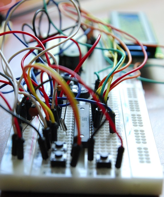
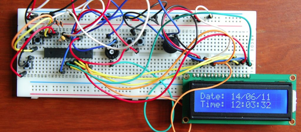
This is my first project to program a micro-controller. For this project I have used an ATMEGA8 micro-controller and BASCOM as programming language. You can use BASCOM IDE for free, as long as the code for the Micro-controller stays under the 4kb limit.
I did my prototyping on a breadboard, later on I will convert this breadboard design in a PCB design and build a real PCB board for this clock.:
The code is very basic, some simple things like using interrupts while adjusting time or date are not ‘yet’ implemented. My main purpose for this project was understanding the process of programming a micro-controller, prototyping a design and building a PCB board myself.
The components that you need for this project are:
- Breadboard
- 32.768kHz Watch Timing Crystal
- Star Micronics TMB-05 Buzzer
- 5Volt
- HD44780 1602 16×2 LCM Character LCD Display
- few capacitors, 0.1uF 50V & 22pF
- Jumper wires, a lot!
- resitor 330Ohm and a red led 3,5V
- 10K potentiometer
- Atmel ATMEGA8-16PU 8-bit Microcontroller IC
Here you can download the BASCOM source code of this project:
alarm clock LCD V1-5 Source Code
I have designed the PCB in Fritzing A nice and easy to use tool to convert a breadboard design into a PCB.
Step 1, design the breadboard:
Step 2, convert the design to a PCB:
Step 3, I’ve used the copper fill option to complete my PCB design for printing:
Next is to make a PCB with the “transfer toner inkt” technique. I have used the following tutorial to create my PCB: http://www.riccibitti.com/pcb/pcb.htm
Step 1, print the layout with “TV programma” paper on the PCB:
Step 2, solve the copper, for this I have used Sodium Persulphate. But there are many other products that will do the job:
Step 3, clean the toner with nail remover or acetone:
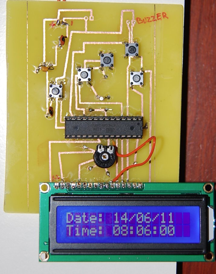
Next steps to finish my alarm clock is to drill the holes and solder the components. After drilling the holes I discovered a fatal error in developing the PCB. I forgot to print the design in mirror, so I got the design the wrong way on the PCB 🙁
Ohhh well, it is a prototype so I solder the components on the PCB side where the copper is ;-). After soldering all components my clock was up and running! A nice little project and I have learned a lot.
My next project is to program a ATmega 324-20PU microcontroller to read a SIRF 3 GPS module and write the data to a SD card.


4 Comments
Mancave
augustus 3, 2011 at 2:58 pmHi Ronald, dit is nou echt een project voor op Mancave. Heb je zin om te bloggen op hét weblog voor elektronica- en techniekfans? Je kunt er €50,- shoptegoed mee winnen bij Conrad (http://www.conrad.nl).
Zie voor meer info http://mancave.conrad.nl/jouwpost/
rbruinsma
augustus 3, 2011 at 4:49 pmDat ga ik zeker doen!
cosmin
november 14, 2012 at 8:01 pmhy
could you post a schematic of this project .. thanks
rbruinsma
december 3, 2012 at 11:43 amhi, sorry but I cannot find the schematics anymore